AdSense

Friday, July 14, 2017

1 - Raspberry Pi and Twitter API: text mining from Twitter stream with Twython


RASPBERRY PI AND TWITTER API: TEXT MINING FROM TWITTER STREAM WITH TWYTHON

- Layout for this exercise:


1 - Introduction

- The goal of this exercise is to get the Raspberry Pi interacting with Twitter in different ways.

- Raspberry Pi can run several libraries from the Twitter API. In particular, in this case Twython will be used.

- Along this exercise Raspberry Pi will write a Twitter message, also filtering some text from a Twitter stream and launching a message, and finally blinking a LED when an specific word is detected.


2 - Registering a Twitter app

- First all, let's assume that there is a valid Twitter account available.

- The first step to create a Twitter app and enabling the access to the Twitter API is to register it here :

https://apps.twitter.com/


- Signing in with Twitter account credentials:


- Creating a new app:


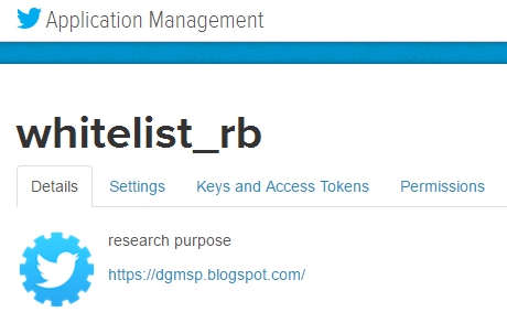
- Some data (name, description of the app, website, ... ) must be provided and eventually the app whitelist_rb is created:


3 - Authentication keys

- During the process of registering the Twitter app 4 keys are created for authentication, and these keys must be written down or copied carefully, keeping them private to be used later at the Python program.

- The purpose of these 4 keys is to ensure that the transmission of the messages are properly authenticated whenever the app accesses the Twitter API.

- The initial two keys are created automatically, Consumer Key (API Key) and Consumer Secret (API Secret):


- Also, and Access Token is created by the user:


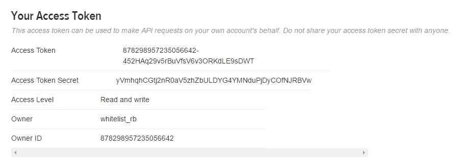
- So 2 additional keys are created, Access Token and Access Token Secret:


- To sum the 4 keys up into a single text, the initkeys.py program is used (let's notice that the keys have been renamed as c_k, c_s, a_t, a_s):


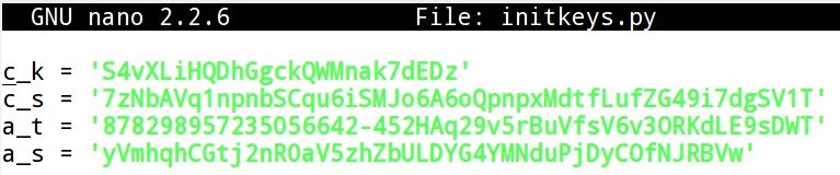
* These values are no longer valid because the application was deleted after publishing this post.


4 - Installing Twython

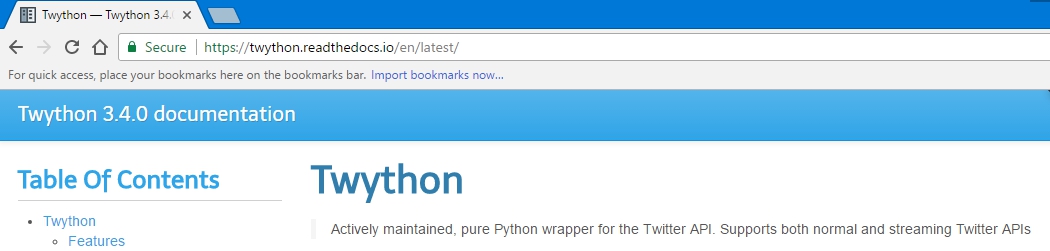
- Twython is a Python wrapper for the Twitter API, allowing both querying data into the Twitter messages stream as well as uploading images, updating status, changing users settings, etc ...

https://twython.readthedocs.io/en/latest/


- To install Twython on the Raspberry Pi follow these two commands (pip is an installer for Python packages):


5 - Publishing a Tweeter message

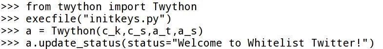
- Now, let's publish a tweet from the Raspberry Pi using a Python script with the interactive mode:


- Almost immediately the tweet is published:


- Let's analyze the code. First, the Twython class is imported:


- Then, the 4 keys are invoked using execfile and passing as a parameter the file initkeys.py, what contains or defines the 4 authentication keys:


- Constructing the Twython object (a) and passing the 4 keys as parameters:


- Finally, update_status allows to pass a text or message as a parameter to the Twython object:


6 - Text Mining and Sentiment Analysis

- Text Filtering or Text Mining with Twython Streamer is a very powerful tool offered by the Twitter API that can be applied to the so called "sentiment analysis".

- Sentiment analysis (sometimes known as opinion mining or emotion Artificial Intelligence) refers to the use of natural language processing, text analysis, computational linguistics, and biometrics to systematically identify, extract, quantify, and study affective states and subjective information. Sentiment analysis is widely applied to voice of the customer materials such as reviews and survey responses, online and social media, and healthcare materials for applications that range from marketing to customer service to clinical medicine.

https://en.wikipedia.org/wiki/Sentiment_analysis

- Twitter can be used as a valid online indicator of a very diverse range of sentiments, for instance related to politics, music, sports, brands, art, commerce, trends, religion, etc ...

- Twython Streamer object class allows to examine public Twitter streams.

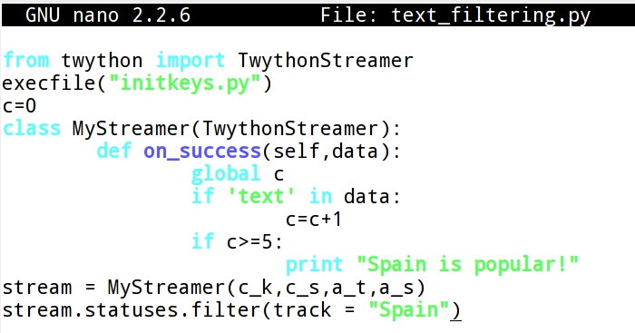
- In the next Python program a class MyStreamer is written so that once the term "Spain" is detected at least 5 times on the stream of Twitter messages an alert or message is launched:


- Giving permissions to the Python program to be run:


- Executing the program:


- Now, 5 messages are created including the word "Spain":


- As a result, the program launches the message "Spain is popular!"


- Let's analyze the code of the program. First, the TwythonStreamer is imported:


- The 4 authentication keys are assigned with execfile passing the file initkeys.py as a parameter:


- Then, the class MyStreamer (extension of TwythonStreamer) is written, what counts from 0 to 5 the times that an specific text ("Spain") matches the content of the Twitter messages stream. Also, when the counter arrives to 5 a message is printed ("Spain is popular!"):


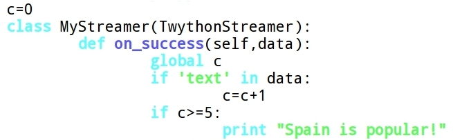
- The 4 keys are passed as parameters to the class:


- Finally, the method statuses.filter() searches for the text "Spain" in the Twitter stream:


7 - LED blinking after publishing a tweet with an specific text

- The layout for this section of the post connects a red LED to the Raspberry Pi module:


- A program is created so that the Raspberry Pi responds by blinking a LED starts whenever the text "fire" is detected into the Twitter stream:


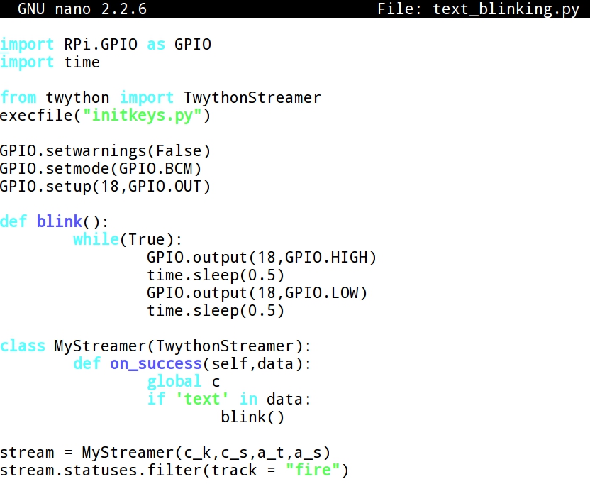
- Giving permissions to run the program:


- Running the program:


- Sending a tweet with the text "fire":


- As a consequence of publishing a Twitter message with the text "fire" the red LED starts blinking, as it can be checked in this video:


10 - Arduino: sensing light with a Photoresistor


ARDUINO: SENSING LIGHT WITH A PHOTORESISTOR

- Layout for this exercise:


1 - Introduction


The purpose of this exercise is to demonstrate how an Arduino board can be used to implement a safety measure consisting of establishing a line between a source of light (LASER or flashlight) and a photoresistor, so that when the light line breaks the alarms are triggered:

https://www.youtube.com/watch?v=mr834Cs9ncs

https://www.youtube.com/watch?v=KX2_LCUkhDs


photoresistor is a light controlled variable resistor, occurring that the resistance decreases with increasing incident light intensity, exhibiting photoconductivity.

- A photoresistor can be applied in light sensitive detector circuits, and light and dark activated switching circuits.

https://en.wikipedia.org/wiki/Photoresistor


- The schematics for this exercise is pretty simple, the only remarkable issue is to connect one of the legs of the photoresistor to the analog pin A0, where the light level readings are received.


2 - Code

- Code for this exercise:


- Let's analyze the code.

- First of all, the pins for the photoresistor (A0), buzzer (11) and RGB LED (3,5,6) are set:


- The photoresistorPin is directly connected to the analog A0, so the input reading measures the light received from the enviroment:


- If the reading is below the threshold 500 nothing happens, for instance when a LASER  or a great source of light is pointing to the photoresistor.

- However, if the reading goes above the threshold 500, for instance when the light line of sight is broken between the source of light and the photo cell, both the buzzer alarm and the Colors() function are triggered, and also an ALARM message is printed at the serial monitor:


- Finally, the functions Colors() and noColors() determine the combination of the RGB LED lights when the alarm is triggered and when the system runs normally.


3 - Running the program

- The serial monitor displays readings from the analog pin A0, showing an ALARM message only when the reading goes above the threshold 500:


- Testing the circuit, in this video it can be checked how the system is quiet when a flashlight points to the photoresistor. However, as expected all the alarms go off when the flashlight is retired:


9 - Arduino: Shift Register


ARDUINO: SHIFT REGISTER

- Layout for this exercise:


1 - Introduction

- The 74HC595 Shift Register (SR) used in this exercise is an Integrated Circuit (IC) with 8 digital outputs that can be controlled with just 3 digital pins of the Arduino. To increase the number of digital outputs multiple SR could be daisy-chained, allowing unlimited number of outputs with the same 3 digital pins of the Arduino.

- Pinning of the 74HC595 Shift Register:

https://www.arduino.cc/en/uploads/Tutorial/595datasheet.pdf


- In this exercise two examples are explained using a Shift Register chip connected with an Arduino board.


2- Stepping up and down 8 red LEDs 

- The goal of this fist exercise is to design a lighting sequence of 8 red LEDs from first to last and in reverse order.

- Arduino sketch:


- Let's analyze the code.

- The SR uses the SPI (Serial Peripheral Interface) serial connection with 3 pins:


- A global variable is used to send data to the SR:


- The 3 pins are set in output mode:


- The loop includes the function UpDown():


- The Serial Peripheral Interface (SPI) has a clock line that controls the speed of the data transfer. shiftIn() and shiftOut() are commands used to access parts that use the SPI interface.

- shiftOut() shifts out a byte of data one bit at a time, starting from either the most (in this case, MSBFIRST) or least significant bit. Each bit is written in turn to a data pin, after which a clock pin is pulsed (HIGH and LOW) to indicate that the bit is available.

- The shiftWrite() function that allows to put the SR outputs into HIGH or LOW state is composed of this subfunctions:

  • bitWrite() makes individual bits of "data" (a byte) on/off,  where "pin" is the SR output from 0 to 7 and "state" is either HIGH or LOW, 
  •  shiftOut() shifts out a byte of data one bit at a time, starting from either the most (in this case MSBFIRST) or least significant bit. Each bit is written in turn to a data pin, after which a clock pin is pulsed (HIGH and LOW) to indicate that the bit is available.
  • Toggling the pinLatch the shift register makes appear the data to the outputs, activating the high to low transition.


- The function UpDown() defines how the 8 red LEDs are lighted one after the other in two consecutive sequences (up and down), using the shiftWrite function for each LED (from 0 to 7) and a delay of 750 milliseconds:


- Testing the circuit and the code, the sequence of 8 LEDs light consecutively stepping up and down:


3 - Binary counter

- The goal of this exercise is to display the 0 to 255 binary bit patterns using the 8 red LEDs.

0 =     00000000
1 =     00000001
2 =     00000010
3 =     00000011
4 =     00000100
5 =     00000101
.........................
.......................... 

253 = 11111101
254 = 11111110
255 = 11111111


- The Arduino sketch: 


- Let's analyze the code.

- The first part is identical to the previous exercise, so we will go directly to the section related with the function BinaryNumbers().

- BinaryNumbers() function is called into the loop():


- The function BynaryNumbers() increases every 1 second the value of the data, and writes out (shifts out, better said) that data to the 8 red LEDs:


- Testing the circuit and the code, the 8 red LEDs show the numbers from 0 to 255 in a binary representation :