AdSense

Tuesday, August 1, 2017

Thinger.io IoT platform (2): controlling a Raspberry Pi from a smartphone Android application


CONTROLLING A RASPBERRY PI FROM A SMARTPHONE ANDROID APPLICATION

- Layout for this exercise:


* This exercise is based in the previous one


1 - Introduction

- The goal of this exercise is to control remotely a red LED connected to a Raspberry Pi device that has been added to the open source IoT platform thinger.io.

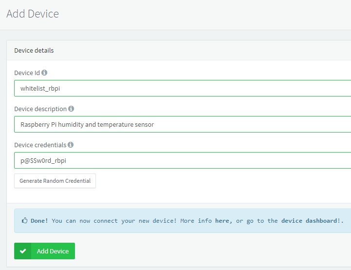
- A device token will be generated to control the red LED from a smartphone using the Android thinger.io application.


2 - Installig WiringPi at the Raspberry Pi

- WiringPi is a PIN based GPIO access library written in C for the BCM2835 used in the Raspberry Pi. It’s released under the GNU LGPLv3 license and is usable from C, C++ and RTB (BASIC) as well as many other languages with suitable wrappers.

http://wiringpi.com/


- Let's install WiringPi at the Raspberry Pi. First of all, to work with the git-core repository:


- Downloading WiringPi:


- Fetching an updated version:


- All the folders and files have been installed:


- Building the application:


- It is important to notice the NOTE warning that to compile programs it is necessary to add -lwiringPi

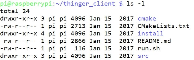
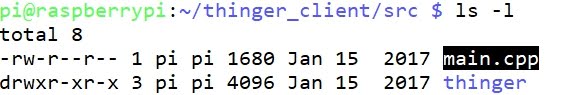
- Moving the library wiringPi.h to the folder thinger_client/src:


3 - Writing the program

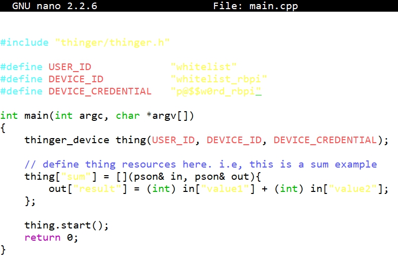
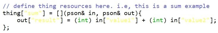
- The main.cpp program used in this exercise:


- Let's analyze the program.

- Including the libraries:


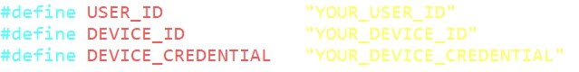
- Providing parameters to connect to the platform thinger.io:


- According with WiringPi pin numbering scheme the pin GPIO 17 corresponds to 0:


- Starting the connection of the device, passing the already defined parameters:


- The pin GPIO 17 is set as OUTPUT mode:


- The device will take 2 possible input modes: HIGH (LED on) and LOW(LED off):


- Starting the application:


4 - Running the application

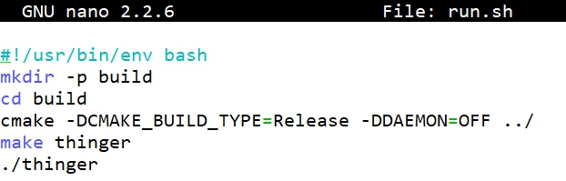
- Before running the application, and in order to perform a correct compilation two lines must be modified at the configuration file CMakeLists.txt, indicating that the -lwringPi option is called:


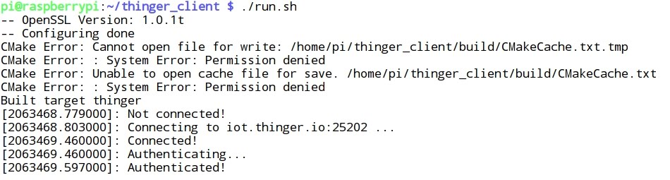
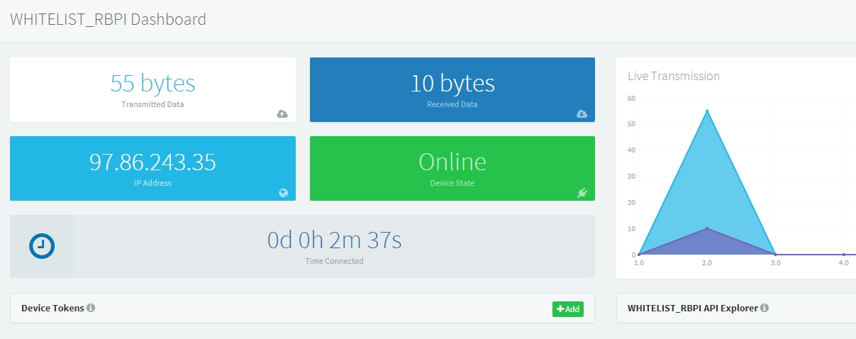
- Running the application, finally the connection is achieved between the Raspberry Pi device and the IoT platform thinger.io:


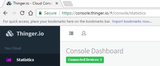
5 - Controlling the Raspberry Pi device from the IoT platform website

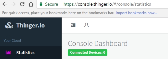
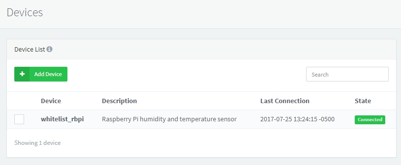
- Signing in the thinger.io website (see previous exercise), a new device is found. 

- The Boolean input can take two values: 0 (LOW = LED off) and 1 (HIGH = LED on):


- By default the red LED is off, with a value "in":false


- Switching the Boolean button the red LED turns on and the "in":true


- At the last point (7) a video will show the final testing of this exercise.


6 - Controlling the Raspberry Pi device from a smartphone Android application

This Android application allows controlling IoT devices connected to the thinger.io platform, and can be easily installed in an smartphone from Google Play: 


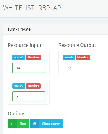
- In order to use the application a device token is required. Going back again to the web dashboard of the thinger.io platform, clicking OK:


- A device token is automatically generated. 


Clicking ShowQRCode:


- Now, the QR code is scanned from the smartphone using the thinger.io application. Once scanned, the application can be used for controlling the Raspberry Pi remotely.


7 - Testing the exercise

- This video shows the successful operation of the exercise:


Thinger.io IoT platform (1): connecting a Raspberry Pi device to the cloud


CONNECTING A RASPBERRY PI DEVICE TO THE CLOUD

- Layout for this exercise:


1 - Setting a Thinger.io account

- Thinger.io is a free and open-source platform for the Internet of Things:

https://thinger.io/

- Thinger.io provides a ready to go scalable cloud infrastructure that can be controlled with an easy to use admin console, or integrated into a business logic with REST API. 

- The entire project is open-source and does not depend on any specific hardware, what avoids the need to select a compatible vendor hardware:


- Signing up for a Thinger.io account, a name, email and password must be provided:


2 - Adding a device

- At first no device is connected:


- Adding a device:


- Some parameters must be entered, like Device Id, description and credentials (the last one can be generated either manually or randomly):


- For accessing the Dashboard just click the words "device dashboard". As expected, no data/output is available at this moment:


3 - Connecting Raspberry Pi 3 to Thinger.io

- Going to the Raspberry Pi command line, let's install some updates and dependencies:


- Compiler for C and C++:


CMake is a cross-platform build system generator:


- libssl-dev package is part of the OpenSSL project's implementation of the SSL and TLS cryptographic protocols for secure communication over the Internet, containing development libraries, header files, and man pages for libssl and libcrypto:


- Finally, downloading the thinger-io application from GitHub:


- Unzipping:


- Renaming the folder Linux-Client-master to thinger_client:


- The folder contents some files and subfolders:


- Inside src there is the main C++ program of the thinger.io application:


- Editing:


 - The library thinger/thinger.h allows to connect the Raspberry Pi to the thinger.io IoT Platform:


 - These 3 parameters must be introduced from the thinger.io account creation at point 2 (Adding a device) of this exercise:


- Eventually, the main.cpp file is like this:


- Let's notice that this application simply adds two numbers and outputs the result


- pson is a variable type that can contain booleans, numbers, floats, strings, or even structured information like in a json document.

- The operator = defines a function that has both input and output. In this case the function takes two different pson parameters. One for input data and another one for output data.

- The pson structure can store values with keys, like any json document. The result provides a value in sum key, that it is translated to json when accessed them from the API.


- Going back one level into the folder path, there is the script run.sh:


- Giving execution permissions to run.sh:


- Running the script, finally the connection between the Raspberry Pi device/application and the Thinger.io IoT platform is successful:


4 - Testing and running the application

- After performing previous steps, now the connected device whitelist_rbpi is found at the Console Dashboard:


- Clicking View API two values can be introduced, and clicking Run the sum of the two numbers is displayed:


- Clicking Show query displays the REST API calls done by the console while interacting with the device. These calls can be used and integrated in other programs, like clients in .NET, PHP, Node.JS, C++, C, bash, ...:


Friday, July 14, 2017

8 - Raspberry Pi and PIR (Passive Infrared): motion detection and notification to Gmail


RASPBERRY PI AND PIR (PASSIVE INFRARED) MOTION DETECTION AND NOTIFICATION TO GMAIL

- Layout for this exercise:


1 - Introduction


- The goal of this exercise is to use a Raspberry Pi board with a Passive Infrared (PIR) motion detector to sense movement of people, animals, or other objects, and send an email notification when an intruder is detected. 

- A PIR sensor is an electronic device that measures infrared light radiating from objects in its field of view.

- PIR sensors are commonly used in burglar alarms and automatically-activated lighting systems.

- Further information about PIR sensors:

https://learn.adafruit.com/pir-passive-infrared-proximity-motion-sensor/how-pirs-work

https://en.wikipedia.org/wiki/Passive_infrared_sensor


2 - Schematics

-  The PIR sensor has got 3 pins that are connected to the Raspberry Pi board in this way:

  • VCC = pin4 (5 V) 
  • GND = pin34 (GND)
  • Sensor = pin11 / GPIO17

- Also, there is a red LED connected to the pin13 / GPIO27 and pin9 (GND) that blinks after detecting movement:


3 - Code

- This is the Python code used in this exercise:


- Let's analyze the code.

- First, some Python libraries are imported for the email notification:


- The pins are assigned to the sensor (in) and the red LED (out) according to the previously explained schematics:


- The PIR sensor is initially set to 0, and then takes its value from the PIR sensor input. When the status changes to 1, the subsequent actions are performed:


- Immediately a notification email is sent. For that purpose some data must be introduced in the code, for instance the email account and password (blurred in the next picture), and the message to be sent:


- Also, when the variable 'status' takes the value 1 (movement is detected) a message is printed on the screen and the red LED starts to blink constantly:


4 - Running and testing the program

- When the program is run and the PIR sensor detects some movement a message is printed (the number 1 corresponds to the value of the variable 'status') and an email is sent:


- Testing the circuit and the code in this video: